Introduction
The Rankine cycle has become the goto process in the vapor power plants. In contrast to the Carnot cycle, this method of power generation provides more value to the outcome of the process. Its ability to increase the working temperature, providing high-quality steam with less moisture content to the turbine, and much easier handling of steam and water are some of the positives that contribute to the overall efficiency of the process.
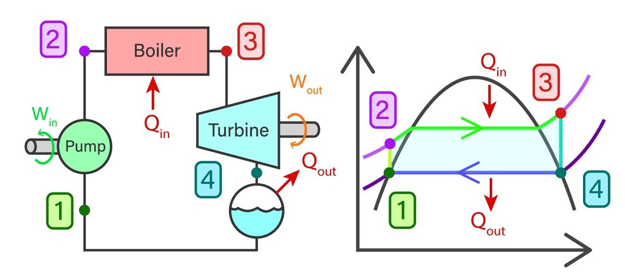
Usually, a power plant consists of four major components in general. They are a feed pump, Boiler, Turbine, and Condenser. Rankine cycle reveals the state of water, Working temperature, and pressure, entropies, and enthalpies at each stage of the closed-loop process.
Ideal Rankine Cycle
The ideal cycle consists of 4 major processes and each of them is reversible processes.
- 1-2 Isentropic compression in the feed pump
- 2-3 Constant pressure heat addition in the boiler
- 3-4 Isentropic expansion in the turbine
- 4-1 Constant pressure heat removal in the condenser

Saturated water from state 1 will enter the feed pump. The feed pump will compress the saturated liquid isentropically to the operating pressure of the boiler. The temperature of the liquid will increase marginally and by now the liquid has shifted from saturating level to a compressed state. Thereafter compressed liquid from sate 2 will head to the boiler. Here the liquid will transform to superheated steam at a constant pressure. As a result of this, the temperature of the steam will increase drastically. Then superheated steam from state 3 will go past the turbines to produce work. This an isentropic where the pressure and the temperature will decrease considerably. At the end of the process, steam has now become a liquid-vapor mixture. Finally, the mixture from stage 4 will go through the condenser to produce saturated liquid in a constant pressure process.
Actual Rankine Cycle
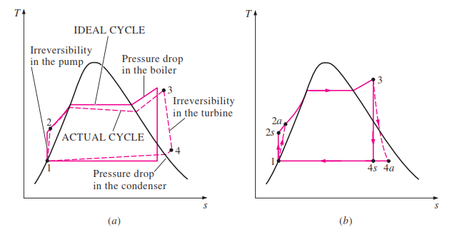
It is impossible to achieve ideal conditions in vapor power plants. So, there is always a dip in efficiency in real situations. Fluid friction is one such effect that creates inefficiencies in the cycle. This will lead to pressure losses in the boiler and the condenser. A pressure drop in the boiler will result in low-pressure steam to the turbine which decreases the work output. As a result of pressure loss in the turbine, the feed pump will require a little more work input than the anticipated input. The other major cause of concern is heat losses throughout the cycle. This will result in more energy requirements than ideal conditions.
T-S Diagram
In an ideal Rankine cycle, state 1 to state 2 will be an isentropic process and a very little temperature is possible as well. At the same time, the pressure will automatically increase via the feed pump. State 2 to state 3 is a constant pressure process. As the boiler provides heat to the liquid it will shift to superheated steam. Therefore both temperature and entropy will increase drastically. State 3- 4 is an isentropic process where the temperature of steam decreases drastically due to work created on the turbine. Pressure too drops considerably. State 4 to state 1 is processed under constant pressure here entropy of the system reduces as the vapor-liquid mixture turns into saturated liquid. Temperature is not going to vary in the ideal cycle as this will only reject latent heat.
The actual Rankine cycle T-S diagram is very much similar to that of the ideal cycle except for a few variations. Here Pump and the turbine will not act isentropically. The pump will require more work in and the turbine results in low work out. These two processes aren’t reversible anymore. Hence the entropy of the following stages will have higher entropy.
P-V Diagram
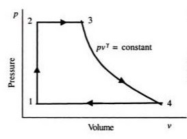
The feed pump will elevate the pressure of the saturated liquid in the process related to state 1 to state 2. There is no change in volume in the process. State 2 to state 3 is a constant pressure process. Since liquid converts to steam, the volume of the system will increase considerably. State 3 to state 4 is an isentropic expansion process. As the name suggests the volume of the system will increase and pressure drop occurs as it passes through the turbine. The final step which is stage 4 to 1 occurs in the condenser with no pressure drop. As the saturated steam converts to the saturated liquid, the volume of the system will decrease considerably.
Rankine Cycle Thermal Efficiency (ηth)
Considering the isentropic behavior in an ideal cycle, the following equations can be derived using enthalpies.
WPump = Work in = ℎ2 −ℎ1
QBoiler = Heat in = ℎ3 −ℎ2
WTurbine= Work out = ℎ3 −ℎ4
QCondenser = Heat out = ℎ4 −ℎ1
Thermal efficiency is defined as ηth =(Work net) / (Heat in)
Work net = Turbine out – Pump in
Work net = h3 + h1 – h4 – h2
Heat in – Heat out = h3 + h1 – h4 – h2
Hence,
Work net = Heat in – Heat out
ηth= 1 – (Heat out) / (Heat in)
The actual cycle is going to vary from the ideal cycle. Therefore the actual condition of the pump and the turbine should be taken into account to determine the efficiency in a real Rankine cycle.
Using Adiabatic Efficiencies of the pump (𝜂𝑃) and the turbine (𝜂𝑇) actual work related to these scenarios can be determined. Here ‘s’ refers to isentropic states and ‘a’ refers to actual states.
𝜂𝑃 = isentropic work in / Actual work in
= (ℎ2𝑠 −ℎ1) / (ℎ2𝑎 −ℎ1)
𝜂𝑇 = isentropic work out / Actual work out
= (ℎ3 −ℎ4s) / (ℎ3 −ℎ4a)
The actual efficiency of the cycle will always be somewhat lower than that of an ideal cycle. In order to calculate the actual thermal efficiency, these efficiencies must be used in the equations.
Reheat Rankine cycle
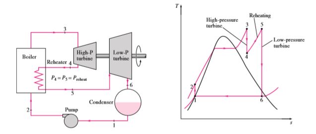
As the name suggests, in this cycle, the steam that comes out from turbine 1 will go through the boiler to reheat the already expanded steam. At the next stage, the reheated stem will go past another turbine to produce more work. Steam from the boiler will expand in a high-pressure turbine. Since the turbine pressure is high steam that comes out of the turbine will have higher pressure in contrast to the normal Rankine cycle. Steam will once again go through the boiler to gather heat and pressure. Then reheated steam will expand in a low-pressure turbine to produce work and then lower the pressure to condenser operating pressure. The total heat to the system will be the heat gathered in both processes. The total work output is equal to the sum of work performed in both expansions.
Regenerative Rankine Cycle
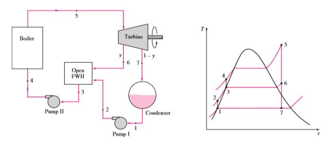
In a traditional Rankine cycle, feed water to the boiler enters at a low temperature. Feeding the water at a relatively high temperature can increase the overall efficiency of the cycle. Here some portion of the steam generated from the boiler will go past the turbine as usual and will expand to Condensor operating pressure itself. The remainder will expand partially. Fully expanded steam will go through the condenser. Condensed water along with partially expanded steam will mix in a heat exchanger to produce water at a high temperature. The mixture will be pumped into the boiler to repeat the cycle.